
Output characteristics of an n-channel MOSFET 
Procedure
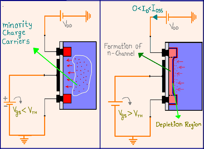
Fig. 1. Gradual channel approximation
MOSFET Experiment Procedure
Set the MOSFET Parameters:
- Adjust the width (W) and length (L) of the MOSFET channel using the input fields. For example, set W = 1E-6 m and L = 1E-7 m.
- Set the mobility (μ) value. In this case, use μ = 1400 cm²/V·s.
- Set the maximum drain-to-source voltage (VDS,max) to 10 V.
Configure the Gate-to-Source Voltages (VG):
- Enter the desired VG values in the input fields. You can set multiple values, for example, from 2 V to 11 V in steps of 1 V.
Set the Material Properties:
- Specify the material parameters such as the work function (φm), electron affinity (χs), and oxide thickness (tox), among others.
- Use typical values like φm = 4.08 eV, χs = 4.05 eV, tox = 3 nm, and εox = 4.
- Set semiconductor parameters such as εsemi (permittivity of the semiconductor), NA (acceptor doping concentration), and temperature (T).
Click on the "Replot" Button:
- Press the "Replot" button to generate the output characteristics curves, which plot ID (drain current) versus VDS for each selected VG.
Analyze the Output Characteristics:
- Observe how the drain current (ID) varies with the drain-to-source voltage (VDS) for different gate voltages (VG).
- Identify the different operating regions (cutoff, linear, and saturation) for each curve.
Optional - Modify Parameters:
- To further explore the MOSFET behavior, modify the parameters (e.g., W, L, VG values) and click "Replot" again to observe the changes in the output characteristics.