
IV characteristics of a PN junction diode 
Procedure
- Gather the required equipment:
- PN junction diode
- Variable DC power supply
- Ammeter
- Voltmeter
- Connecting wires
- Resistor (optional, for current limiting)
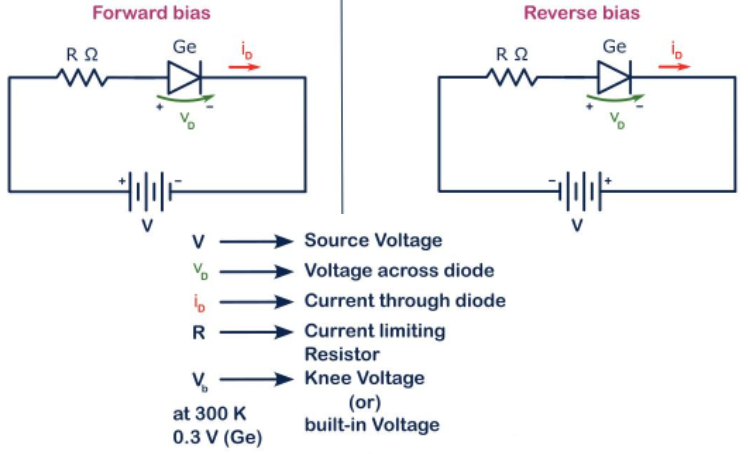
Fig. 1. Circuit diagram
- Set up the circuit for forward bias:
- Connect the anode of the diode to the positive terminal of the power supply.
- Connect the cathode of the diode to one terminal of the ammeter.
- Connect the other terminal of the ammeter to the negative terminal of the power supply.
- Connect the voltmeter across the diode to measure the voltage drop.
Procedure
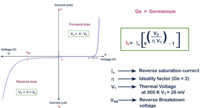
Fig. 2. Transfer curve / V-I characteristics of diode
- Gradually increase the power supply voltage from 0V and record the current through the diode and the voltage across the diode at each step.
- Continue increasing the voltage until a significant increase in current is observed, indicating the forward threshold voltage.
- Turn off the power supply and set up the circuit for reverse bias:
- Connect the anode of the diode to the negative terminal of the power supply.
- Connect the cathode of the diode to one terminal of the ammeter.
- Connect the other terminal of the ammeter to the positive terminal of the power supply.
- Connect the voltmeter across the diode to measure the voltage drop.
- Gradually increase the reverse bias voltage from 0V and record the current through the diode and the voltage across the diode at each step.
- Continue increasing the voltage until the breakdown voltage is reached, where a significant increase in current is observed.
- Turn off the power supply and disconnect the circuit.
- Plot the IV characteristics of the diode using the recorded data, showing both the forward and reverse bias regions.
This procedure helps in understanding the behavior of a PN junction diode under different biasing conditions, providing practical insights into its IV characteristics.